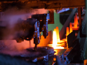
Rapid Die Casting
Rapid die casting through specialized tooling is an approach to die-cast prototyping that has been used by foundries for several decades, but the advent of Stereolithography and Computer Aided Design modeling are driving an interest in the recent past into the application such software provides. For instance, using a Stereolithography model, an H-13 steel die can be cast to a net-shape within a fraction of time as opposed to what is required to cut tool steel.
Further geometrical shapes can be added using secondary machining. An advantage of this method is that it can provide die-cast parts in short-runs, as parts are processed as a casting with ideal thermal transfer and physical properties identical to that of end components. Rapid die casting process can provide cost-efficiencies as well, as opposed to plaster mold casting, especially if the quantities required exceed 1000. As the parts are run inside a die-cast press, a large number of components can be produced within a short time span and that adds to considerable economies of scale.
This largely accurate method to provide short runs is capable of producing a casting with fine details and excellent surfaces. The die casters can accommodate parting line, with side die pulls for manual loading of a material used in the approach to rapid prototyping. Yet again, that side pulls approach is not advisable for use with thin, tall-standing component details or cast-in waterlines. Typically, lead times of rapid casting process ranges from 5 to 8 weeks, which also depends on the complexity and size of the required end part.
In case H13 Tool Steel is used for that, and an initial geometrical pattern is created through CNC or SLA with shrinkage aspects scaled in. The parting lines for that are developed and soft negative durometer is produced in a tool’s shape. In other words, a tool of ceramic material is made specifically for this and then steel is poured into that. The cavity details can be complemented through CNC machining or Electrical discharge machining, if required.
The inserts are conformed and then fitted into a mold base, where the ejection pins are additionally placed. The overflows and gates are machined in and cast die are set to be run inside a standard die-cast press. The components can be run in virtually any die cast alloy, although the surface finishing necessitates a trim and secondary machining as needed.
